Raspberry Fly
A Raspberry Pi based autonomous aerial drone
Software
This is a big, fun and sometimes frustrating part. This is where you implement all the math from the flight instruments section, the communications with the instruments, the motor control and all the logic that keeps the drone in the air. It is quite time consuming and requires a lot of testing in order to minimize the risk of accidents later on. Writing robust software is key to a stable and safe drone. This section doesn't go through any particular implementation of flight controller software in detail, but attempts to explain the tools needed to write that software.
Language
What programming language should we use? Well any language supported by the platform used will do. Python was the natural choice for the Raspberry Fly since it is based on a Raspberry Pi. Also I had no prior experience with Python and thought it would be fun to learn along the way. A case can certainly be made for using a faster language like C, but for me Python was the best choice. Before choosing a language though, make sure that there are libraries available that lets you communicate easily over the I2C-bus.
Connecting to the flight instruments
We won't get anywhere without flight instruments, so let's start by getting them online. Assuming that we use the I2C for communication and that the instruments are physically connected to the flight controller with the I2C clock and data lines (SCL and SDA) we just need power. The instruments (AltIMU-10 v3) on the Raspberry Fly gets their power directly from the Raspberry Pi flight controller (GPIO pins). They can run on anything from 2.5V to 5.5V, but remember that the Raspberry Pi is only 3.3V tolerant! Actually in this case I don't think there is any danger of frying the Pi. If I understand correctly the Pi will drive the I2C lines to a 3.3V high and devices on the I2C will drive them low to communicate. That way the Pi won't be exposed to 5V, but the devices might have problems seeing 3.3V as high if they are expecting a 5V high. But don't take my word for it. Remember that I am a computer scientist and someone once said that the only thing more dangerous that an engineer with a keyboard is a computer scientist with a soldering iron... Anyway, to be on the safe side all devices on the Raspberry Fly runs at 3.3V. If necessary a logic level converter could be used for 5V devices.
With everything powered up we can start connecting to the instruments through software. When using Python we need to install a module that allows us to use the I2C bus and do a bit of setup. By default Raspbian has I2C disabled so let's start by enabling it. Open /etc/modprobe.d/raspi-blacklist.conf in an editor and comment out the lines
blacklist spi-bcm2708
blacklist i2c-bcm2708
by adding a # in front of both lines. Save and close the file. Now edit /etc/modules and add these two lines at the end of the file
i2c-bcm2708
i2c-dev
Save and close the file. This should enable I2C on the next reboot. Now we just need to install a few tools. Use apt-get to install python-smbus and i2c-tools:
sudo apt-get install python-smbus
sudo apt-get install i2c-tools
Now reboot the Raspberry Pi. With the flight instruments attached run the following command on the command line
sudo i2cdetect -y 1
This will show devices connected to the I2C bus.
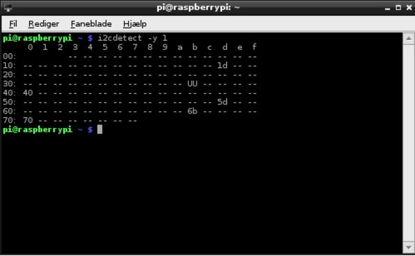
This is for the Raspberry Pi Model B Rev.2. On an older Pi you might need to write 0 instead of 1 at the end of the i2cdetect command. This is because the Model B Rev.2 Pi has two I2C buses numbered 0 and 1. I2C bus number 1 is the one available through the GPIO pins. Bus number 0 should be available through the P5 header group, but no pins are installed by default so this would require that you solder them on yourself. If you do this then the P5 pins are meant to be installed on the backside of the Pi. Anyway, no need for all this. The default I2C-bus will do just fine.
So what are all the weird numbers in the output from i2cdetect? It is the addresses of responding slave devices on the bus. In this case the flight instruments and PWM-driver. The datasheet for the devices will tell you which addresses correspond to which devices.
Communicating with the flight instruments
You may have noticed that we installed a python module called python-smbus. The System Management Bus or SMBus for short is based on the I2C-bus. There are of course differences in the specifications, but they should be compatible for speeds of 100 KHz and below and fortunately the Raspberry Pi I2C-bus runs at 100 KHz by default. So just import the smbus module in your code and you are good to go.
Communication with devices on the bus will be done by reading and writing registers on the devices. Registers differ from device to device, so reading through the datasheet for each device is necessary. No shortcuts here. Some devices need to be setup and powered up before use. Again this will be described in the device datasheet. I have written a small program that can serve as an example.
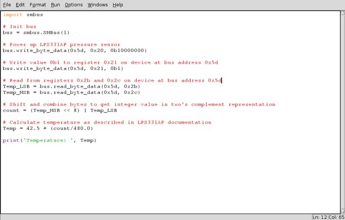
The IMU used on the Raspberry Fly includes a LPS331AP pressure sensor with a bus address = 0x5d. It has three control registers at 0x20, 0x21 and 0x22. Remember that device addresses on the bus need to be unique in order for us to be able to identify the device we want to communicate with, but register addresses only need to be unique on each device. For example we can't have two devices with address 0x5d on the bus since there would be no way to differentiate between them. However two different devices can both have a register with the same address since we identify a register by the combination of device and register address. By the way 0x is the prefix denoting hex numbers and 0b is the prefix denoting binary numbers in Python. Now let's return to the example.
- We start by importing the smbus module.
- We power up the sensor by writing a byte containing 0b10000000 to control register 1 (register address 0x20) on the pressure sensor (device address 0x5d). We do that because that is what the datasheet says we need to do in order to power up. Multiple properties can often be manipulated by writing one byte. In this case it is the 1 at the most significant bit that powers up the sensor. Since we can't write less than 1 byte at a time, be sure that the content of the entire byte is as you want it.
- We now write 0b1 to control register 2 (0x21). This tells the sensor that we are requesting a one off reading.
- The temperature data is store in two bytes at register addresses 0x2b and 0x2c. We read the temperature data's least significant byte and most significant byte from these registers.
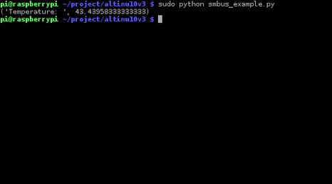
- The temperature is given in units of count and the datasheet tells us how to convert these counts to degrees Celsius, but first we need to combine the most and least significant bytes to one number in units of count.
- Then we can convert from counts to degrees...
- ... and print the temperature.
This is basically how to communicate with the flight instruments and all other devices on the I2C bus. This might look like a lot of work, but storing register addresses in sensibly named variables and putting it all neatly away in classes along with conversion functions and so on, greatly improves both readability and usability of your code.
Control loop
The control loop is at the heart of stable flight. It is in this loop that we make many corrections per second based on flight instrument data in order to keep the drone stable and in the air. It is necessary to know the duration of each iteration precisely (this is the delta t in equations 12 and 13 in the flight instruments section) and to keep an efficient loop that runs at least 50 times a second (preferably > 100). Any less and it will get increasingly difficult to keep the drone stable or even in the air. During each iteration we need to
- Get data from flight instruments
- Find difference between actual and target values.
- Calculate needed corrections
- Apply corrections to motors
Getting the data is simply a matter writing software for communicating with the flight instruments and using it. Finding the difference between actual and target values for properties like roll, pitch and yaw are also easy. Calculating the needed corrections is a bit more difficult. Wouldn't it be nice to have a simple and precise mathematical model of the drone, the world and how they interact? Yes, but unfortunately we don't have one. Such a model would get very complicated quickly and require much more processing power than available on a controller like the Raspberry Pi. PID controllers to the rescue!
PID
PID stands for Proportional Integral Derivative and a PID controller is a control loop feedback mechanism that calculates the error between an actual and a target value and tries to minimize this error by making corrections. Sound familiar? This is exactly what we need!
A PID controller has three components: a proportional, an integral and a derivative component (surprise). Each of these components make their contribution to the final output of the controller which is then used to make corrections to the motor speeds. At the next iteration of the control loop a small time period has elapsed and the drone has now reacted to the corrections applied in the previous iteration of the control loop. New data reflecting this is retrieved from the instruments and the PID controller will once again make correction to minimize the error between actual and target values. Let's have a look at the PID controller in detail:
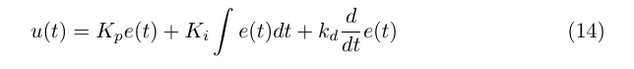
u(t) is the controller output, Kp, Ki and Kd are tunable gains for the proportional, integral and derivative components and e(t) is the error. In pseudo code this could look something like:
Error = target - actual_value
IError = IError + Error * dt
DError = (Error - Previous_error) /dt
return (Kp*Error + Ki*IError + Kd*DError)
The return value can now be used to make corrections to the motors speeds. The real trick is in the testing section where we have to tune the gains (Kp, Ki and Kd) for each PID controller in order to achieve stable flight and a quick responsive drone. Definitely not as easy as it sounds!
The number of PID controllers used depends on what we want to accomplish. For testing purposes it is a good idea to start out simple. One PID for roll and one for pitch. With a target of 0 degrees for both, a quadcopter should be able to balance itself on a testing rig with motors at less than takeoff speed for safety reasons (remember to put a limit in your code that ensures takeoff speed is not exceeded by the PID corrections). Use the net output of the PID's to make corrections to the motors. How you apply the corrections depends on what you are correcting for. For pitch split the output 50/50 and subtract from the front motors and add to the rear motors. The same for roll, except it is left and right motors instead of front and rear.
When feeling comfortable with this, more PID's can be added to control other properties like yaw, vertical speed etc.
PWM
But how do we control the motors? As mentioned in the motor control section it is done by pulse-width modulation. There are several ways to do that with the Raspberry Pi even though it isn't that good at PWM. One option is using software PWM though RPi.GPIO, but this is not very precise and uses some processing power. Another is using RPIO.PWM for semi-hardware PWM. RPIO.PWM uses DMA to achieve a PWM resolution down to 1 microsecond while using little processing power. This actually seems very good. The last option is using external hardware for PWM. The Raspberry Fly uses an external PWM-driver on the I2C bus for precise hardware PWM. I have been very satisfied with this solution although it did take some calibration. As it turns out the internal clock on the PWM-driver did not run at 25 MHz at advertised, but at 28.2 MHz on my particular board. This was easily compensated for, but I did need my oscilloscope for the calibration, so RPIO.PWM might be the way to go for most people. Good RPIO.PWM examples are available here.
Drones are fun but can be dangerous. Use any information on these pages at your own risk