Raspberry Fly
A Raspberry Pi based autonomous aerial drone
Motor Control
When the flight controller knows what it wants the motors to do, actually getting them to do it is obviously key to succes. The motors on a quadcopter are connected to one Electronic Speed Controller (ESC) each. As the name implies the ESC helps control the speed of the motors. An ESC has an amp rating that tells you how much current it can safely handle. It is important to make sure the motors cannot draw more power than the ESC can handle! The Raspberry Fly is equipped with 30 Amp ESCs and motors with a standard current between 15 and 25 Amp and a max of 30 Amp.
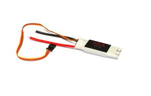
Raspberry Fly ESC:
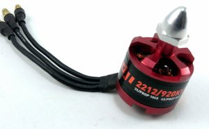
Raspberry Fly motor:
On the input side the ESC has two thick wires for power from the battery and three small wires for control. The small wires are ground (brown on the DJI 30A), +5V (red on the DJI 30A) and signal (orange on the DJI 30A). Make sure you know what color coding is used on you own ESC before hooking it up. If your ESC has a Battery Elimination Circuit (BEC) the +5V wire can be used to power a 5V receiver (the DJI 30A doesn't have a BEC). For control purposes we just need the ground and signal wires.
PWM
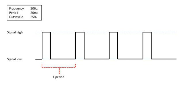
So what kind of signal do we need to send along to the ESC to get the motors spinning? The ESC's are pulse-width modulated so we need to send a Pulse-Width Modulation (PWM) signal. PWM is a widely used technique to control the width of a pulse. If we have a signal with frequency F then each period is 1/F second long and by using PWM we can determine for how long the signal is high during each period. The percentage of a period where the signal is high is also called the duty cycle. Let's look at an example. If we have a 50 Hz signal each period will be 1/50 = 20 ms long. If the signal is high for 5 ms and low for 15 ms each period then the duty cycle is (5/20) * 100 = 25%.
Most ESC's accept a PWM signal in the range of 50 - 400 Hz, but check your ESC datasheet before use. Throttle is controlled by the width of each pulse. Usually a 1ms pulse translates to 0% throttle and a 2ms pulse translates to 100% throttle. It is very important to understand that duty cycle does NOT translate directly to throttle. If we look at the 50 Hz example above a 1ms pulse = 5% duty cycle = 0% throttle and a 2ms pulse = 10% duty cycle = 100% throttle. And these values change at different frequencies of the PWM signal. And again make sure that your ESC actually translates a 1ms pulse to 0% throttle and a 2ms pulse to 100% throttle.
When powered up without a PWM signal the ESC's will start beeping. When supplied with a PWM signal between 1ms and 2ms the beeping will stop.
Remember that the PWM signal frequency needs to be at least as high as the control loop frequency (see software section). No point in doing lots of correction calculations each second if we only send them along 50 times a second (50 Hz). Setting the PWM signal frequency to 200 Hz is recommended.
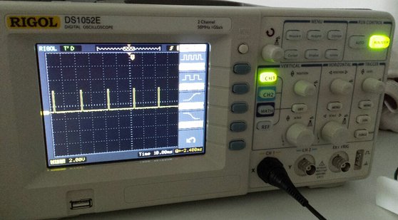
An oscilloscope is not necessary, but it can come in very handy when debugging your PWM signal.
This section explained the basic theory of PWM. Se the programming section for info on doing PWM with the Raspberry Pi
Direction of spin
When testing your motors for the first time you might notice that one of the motors is not spinning in the direction you want. Fortunately it is easy to change that. Simply switch around any two of the three motor wires that you have connected to the ESC output. NEVER switch the two ESC input wires around! That will fry your ESC.
Drones are fun but can be dangerous. Use any information on these pages at your own risk