Raspberry Fly
A Raspberry Pi based autonomous aerial drone
The Flight Instruments
In order to interact with the world we need senses. As humans we have five senses to help us get around and experience the world. The Raspberry Fly is no different. It too needs senses to get around safely and for that purpose it uses flight instruments to collect real world data.
Since we live in a 3D world the Raspberry Fly can move around 3 axis: yaw, pitch and roll:
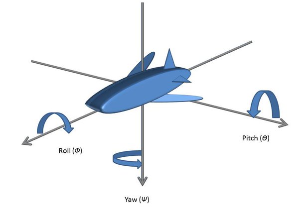
And no, this is neither a mutated shark nor a weird submarine. It is my attempt at drawing an airplane in a 3D coordinate system...
Anyway these are the three axis the plane, and in our case the Raspberry Fly, can rotate around. A onboard gyroscope is used to measure the rate of change around these three axis. It is important to note that it is not the absolute angle but the change in angle that is measured. In a perfect world that would not be a problem, but we do not live in a perfect world and a reasonably priced is gyroscope is not exactly perfect either. That means each measurement contains a small error, which will build up with time. If we try to measure the rate of change in pitch, roll and yaw at time intervals and add them up like:
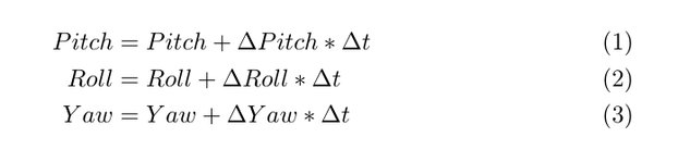
It would be theoretically correct, but because of the accumulating error our estimate of the drones pitch, roll and yaw after 30 seconds would be so far off it would crash. So while the gyroscope will be quite precise in small time intervals (less than a second), it will be useless for sustained flight if we can't counteract the accumulating error.
Enter the accelerometer. The accelerometer measures acceleration, and since we are on Earth it will be under the influence of Earth's gravitational field. When lying at rest it will measure an acceleration of 1G in the direction of Earth's center. The accelerometer returns the measurement in X, Y and Z components (the three orthogonal axis in a 3D coordinate system), and from this information we can calculate an estimation of pitch and roll.
We can define the orientation of the drone as a series of three rotations from an initial position. One rotation around each of the axis of pitch, roll and yaw. These rotations can be represented by the rotation matrices:
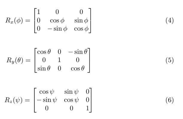
where phi is angle of roll, theta is angle of pitch and psi is angle of yaw. Now this might be a good time to read up on matrices and especially matrix multiplication if you feel a little rusty. Remember that matrix multiplication is associative but NOT commutative.
Assuming a level initial position where the only acceleration felt by the drone is from the Earth's gravitational pull (1G) the output vector from the accelerometer would be (0,0,1). Applying the roll, pitch and yaw rotations would give us the current orientation:
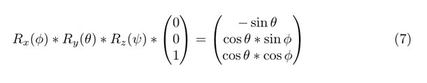
The right hand side of equation (7) is equal to the normalized reading from the accelerometer:
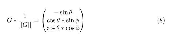
Where G is the output vector from the accelerometer.
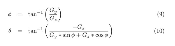
It is possible to solve for pitch and roll (theta and phi):
This was just a quick explanation based on the rotation sequence from equation (7). I highly recommend grabbing pen and paper and working your way through the excellent AN3461 application note from Freescale Semiconductors.
Now that we have roll and pitch angles what about yaw? Well we can't really get a reliable estimate of yaw from the accelerometer. Most of the time the drone will be flying relatively level which means that the z-axis will be parallel or close to parallel with the axis of Earth's gravitational pull. In a situation like this any rotation around that axis (yaw) will have very little to no effect on the accelerometer output. Noise in the accelerometer output will be much greater and any attempt at calculating yaw from that output will yield a result that is all over the place. Useless. This is where a magnetometer comes in handy. A magnetometer measures the direction of the magnetic field around it. In an environment without too much interference from other equipment this will be the Earth's magnetic field. Since the vector of the magnetic field is not parallel with the vector of Earth's gravity (assuming the drone will stay clear of the poles), we can use the output from the magnetometer to get an estimate of the yaw angle:
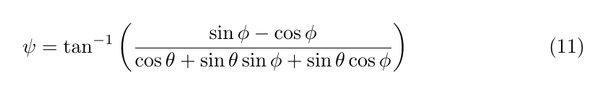
This is called a tilt-compensated heading because it derotates the pitch and roll angles in order to get the correct yaw angle. So now we have yaw right? Well kind of. Once again we have assumed a near perfect scenario where no other magnetic fields than the Earth's are present. However such a scenario is unlikely and the accuracy of our calculated yaw is influenced by magnetic fields in the vicinity of the drone. The unwanted effects are divided into hard-iron and soft-iron effects. Hard-iron effects are those that are constant regardless of orientation. They contribute a constant additive field to the Earth's magnetic field and that makes them relatively easy to compensate for. Soft-iron effects are not constant additive fields, but rather distortions to existing fields. They depend on orientation and are not as easy to compensate. Fortunately it will often be enough to compensate for hard-iron effects to get a reasonably good yaw estimate (The Raspberry Fly only use hard-iron compensation).
But how do we check for hard- and soft-iron effects? One way is to visualize a number of measuring points. Simply rotate the drone in all directions with the magnetometer installed and record the readings. Then use a software package to visualize them, treating each recorded reading as a 3D-point. If no magnetic fields interfere we should get a sphere with center at (0,0,0). Hard-iron effects will move the sphere and the constant additive hard-iron field vector will be equal to the center of the sphere. This vector can be subtracted from the magnetometer readings to compensate for hard-iron effects (effectively moving the center of the sphere back to (0,0,0)). Soft-Iron effects will show as a distortion of the sphere into an elliptical shape. This figure shows hard- and soft-iron effects from the Raspberry Fly:
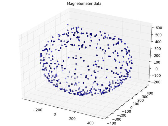
The data is slightly elliptical (soft-iron effect), but good enough for my use. The center can be found by using software to fit the data to a circle and then used for hard-iron compensation. For more information on using the magnetometer to estimate yaw i highly recommend another great application note from Freescale Semiconductors (AN4248). Once again grab pen and paper and work your way through it.
Ok, so now we finally have everything we need to know about the orientation of the drone right? Well not quite. Let's take a look at what we do have:
- Rate of change for pitch, roll and yaw from the gyroscope
- Absolute Roll and Pitch angles from the accelerometer
- Absolute Yaw angle from the magnetometer
The gyroscope data is highly accurate at small time scales, but also seriously prone to accumulating errors (drift) and it is unreliable for sustained stable flight. The accelerometer data is much more reliable at larger time scales (> 1 second) because it can use Earth's gravity as an external reference, but it is prone to noise due to motor vibrations and short high G maneuvers. This helps us because we can combine the data by using gyroscope data for short term precision and accelerometer data for long term stability and drift compensation. This can be done in several ways. At the moment the Raspberry Fly uses a simple complementary filter, but you can also use the better performing, but less intuitive and more calculation intensive kalman filter. As indicated by the name the complementary filter simply lets the gyroscope data complement the accelerometer data. In every iteration of the control loop (more on the control loop in the "Flight Controller" section) we do the following calculations for roll and pitch estimates:
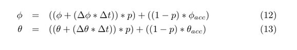
If we look at roll (equation 12), then phi is the current estimate of roll, delta phi is gyroscope output for roll (rate of change), delta t is control loop period (reciprocal of control loop frequency) and phiacc is accelerometer output for roll (absolute). p is a variable that determines how to combine the data from the gyroscope and the accelerometer. A value of 0.95 (a good start) will rely 95% on the gyroscope and 5% on the accelerometer. This preserves the high short term precision of gyroscope data while preventing the drift from long term accumulating errors by using Earth's gravitational field as an external reference through the accelerometer data.
So do we have to go and buy a gyroscope, an accelerometer and a magnetometer? Yes and no. Fortunately these instruments are available as Inertial Measurement Units (IMU). These are small breakout boards with a gyroscope, an accelerometer and sometimes a magnetometer. Just what we need! These can usually be communicated with on an I2C-bus so getting readings are quite easy using a Raspberry Pi. The Raspberry Fly uses an AltIMU10-v3 with 10 Degrees of Freedom (DOF). 3 degrees from the gyroscope, 3 degrees from the accelerometer, 3 degrees from the magnetometer and 1 degree from the barometer.
Just a few notes before rounding up the Flight Instruments section. When going through all the calculations there is plenty of opportunity for small mistakes that will result in a lot debugging frustrations. Be absolutely sure that instrument axis are aligned on the IMU and keep a close eye on which way the positive axis are pointing. The IMU should have axis printed on it for reference, and the calculations depend on the axis orientations in relations to each other. So when absolutely sure about where all instrument axis are located go through the calculation to make sure that no axis need to be swapped around. If you are anything like me, this is the point in the process where you look slighty insane trying to visualize all the axis with your fingers.
Drones are fun but can be dangerous. Use any information on these pages at your own risk